A fluid bed dryer diagram is a visual representation that explains how a fluidized bed drying system is structured and how air and materials move through it.
For engineers, operators, and buyers, understanding this diagram is essential because it simplifies a complex drying process into clearly defined components and flow paths.
1. What a Fluid Bed Dryer Diagram Shows
At its core, a fluid bed dryer diagram illustrates three key elements:
- Airflow path (how hot air enters, flows, and exits)
- Material movement (how particles are fluidized and dried)
- System components (equipment that supports the drying process)
Unlike simple equipment sketches, a proper diagram highlights interaction between air and solids, which is the defining principle of fluidized bed drying.
2. Main Sections in a Fluid Bed Dryer Diagram
2.1 Air Handling System
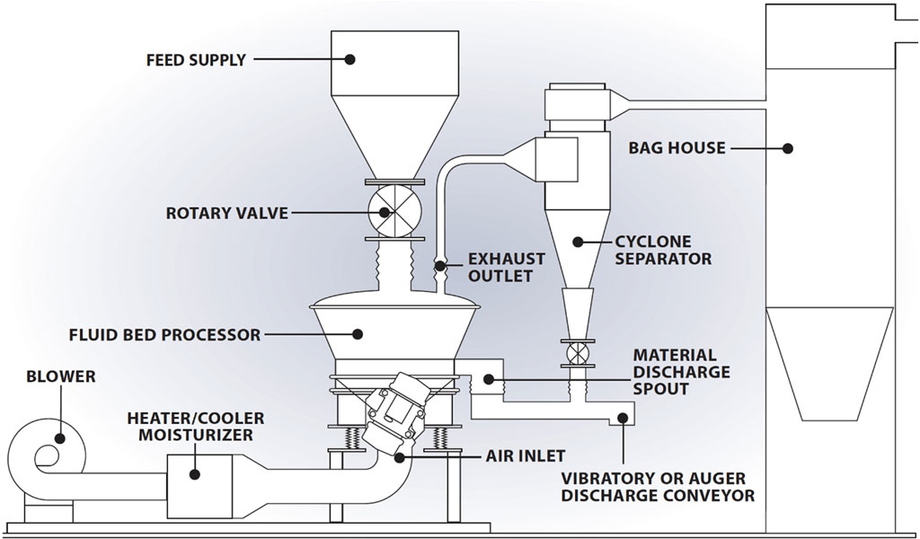
This section is usually shown on one side (often the bottom or left) of the diagram.
Typical labeled elements include:
- Air inlet
- Blower/Fan
- Heater (electric, steam, or gas)
- Air filter
In the diagram, arrows indicate airflow direction:
- Ambient air → filtered → heated → pushed into the drying chamber
This part of the diagram emphasizes air preparation before contact with the material.
2.2 Plenum Chamber
The plenum chamber sits directly below the product container and is clearly marked in most diagrams.
- It acts as a uniform air distribution zone
- Ensures even airflow across the entire bed
In diagrams, it is usually drawn as a box beneath a perforated plate, with arrows spreading evenly upward.
2.3 Perforated Distributor Plate
One of the most important elements in the diagram:
- Shown as a horizontal plate with small holes
- Separates the plenum chamber from the product chamber
Its role in the diagram:
- Converts incoming air into uniform vertical airflow
- Enables fluidization of particles
In schematics, airflow arrows pass through this plate and expand upward.
2.4 Product Container (Fluidization Zone)
This is the central part of the diagram where drying happens.
Key diagram features:
- Particles shown as small dots or a dense bed
- Upward airflow arrows passing through the material
- Sometimes illustrated as a boiling or bubbling effect
This visual represents:
- Particles being lifted and suspended
- Continuous mixing and exposure to hot air
2.5 Expansion Chamber (Freeboard Area)
Above the fluidized bed, diagrams often show a larger open space.
Functions illustrated:
- Allows particles to slow down and settle
- Prevents product loss
In diagrams:
- Airflow arrows become wider and less dense
- Fewer particles are shown
2.6 Exhaust System
At the top or side of the diagram, the exhaust section includes:
- Filter bags or cartridges
- Cyclone separator (optional)
- Exhaust fan
Airflow arrows show:
- Moist air exiting the chamber
- Fine particles being captured before discharge
3. Understanding Flow Direction in the Diagram
A fluid bed dryer diagram is heavily dependent on directional arrows, which indicate:
Airflow
- Bottom → upward → exit
- Represents heated air fluidizing and drying particles
Material Behavior
- Static at start → fluidized → circulating within chamber
Moisture Removal
- Moisture evaporates → carried away with exhaust air
By following these arrows, you can understand the entire drying cycle without reading technical text.
4. Common Diagram Variations
Different types of fluid bed dryers are represented slightly differently in diagrams:
Batch Fluid Bed Dryer
- Single container
- Fixed structure
- Straightforward airflow
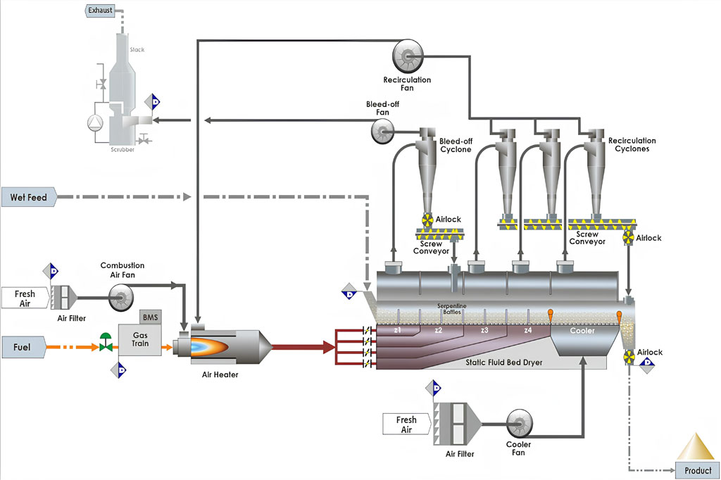
Continuous Fluid Bed Dryer
- Extended horizontal design
- Material moves from inlet to outlet
- Multiple air zones shown
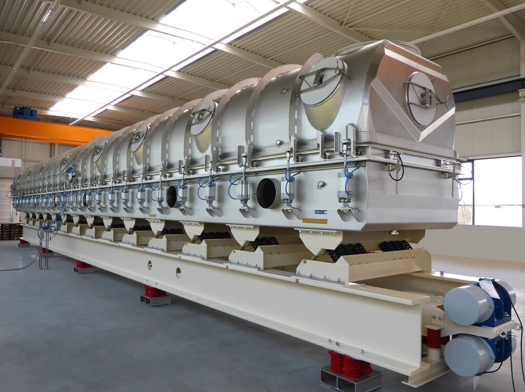
Vibrating Fluid Bed Dryer
- Includes vibration mechanism symbols
- Shows enhanced particle movement
Despite these variations, the core diagram structure remains consistent.
5. Symbols and Notations in Diagrams
A standard fluid bed dryer diagram uses recognizable symbols:
- Arrows → airflow direction
- Dots or particles → material
- Boxes/sections → equipment zones
- Dashed lines → separation or internal boundaries
Understanding these symbols allows quick interpretation of even complex industrial layouts.
DIAGRAM REVIEW
Use the Diagram to Define Process Interfaces
A general diagram helps identify the main air, material and exhaust paths. For an actual project, each path must be connected to measurable feed conditions, product targets, utilities and equipment interfaces.
Material path
- Feed form, particle distribution, bulk density, moisture and flowability
- Batch or continuous loading, residence behavior and discharge arrangement
- Final moisture or cooling target, fines and downstream handling
Air and heat path
- Heat source, inlet-air conditioning and available utilities
- Distributor, bed pressure behavior, exhaust and dust collection
- Drying, cooling or combined sections and any air-recovery requirement
Instrumentation and protection
- Measurements needed for temperature, pressure, airflow and product condition
- Approved alarms, interlocks, cleaning and maintenance access
- Dust, volatile, containment and local environmental or safety requirements
Drawing boundary: The diagrams on this page are educational schematics. They are not project PFDs, P&IDs, fabrication drawings, control narratives or safety documentation. Final drawings and protective systems require project-specific engineering, calculations and review.
Related Fluid Bed Dryer Resources
- Fluid Bed Dryer Systems
- Fluid Bed Dryer Working Principle
- Vibrating Fluid Bed Dryer
- Vertical Fluid Bed Dryer
Discuss a Fluid Bed Dryer Layout
Send the material and moisture data, capacity, drying or cooling target, process interfaces, heat source, utilities and installation constraints.
Fluid Bed Dryer Diagram FAQs
What is the purpose of the distributor plate?
It distributes process air into the bed. Its design must suit the material, airflow, pressure behavior and required fluidization condition.
Why is an expansion or freeboard area shown?
It provides space above the active bed and influences particle disengagement, carryover and the interface with exhaust collection.
Does every fluid bed dryer use the same layout?
No. Batch, continuous, vibrating, multi-zone and integrated drying/cooling duties can require different material paths, air circuits and controls.
What is needed to develop a project drawing?
Provide representative material data, process duty, capacity, equipment interfaces, utilities, controls, cleaning needs and safety or environmental requirements.