Technical Parameters
| Item | 30 | 60 | 90 | 120 | 150 | 200 | 300 | 500 | 800-1000 | |
| The volume of Container(L) | 100 | 220 | 300 | 420 | 500 | 670 | 1000 | 1500 | By client | |
| Productive capacity(Kg/batch) | 30 | 60 | 90 | 120 | 150 | 200 | 300 | 500 | ||
| Steam | Pressure Mpa | 0.4-0.6 | ||||||||
| Consumption Kg/h | 70 | 140 | 169 | 211 | 241 | 282 | 366 | 465 | ||
| Compressed air | Pressure Mpa | 0.6 | ||||||||
| Consumption m3 /min | 0.3 | 0.6 | 0.6 | 0.6 | 0.6 | 0.9 | 0.9 | 1.1 | ||
| Power of fan(kW) | 5.5 | 11 | 15 | 18.5 | 22 | 22 | 30 | 45 | ||
| Inlet air temperature(℃) | Normal temperature ~120℃automatism adjust | |||||||||
| The yield of material(%) | >99 | |||||||||
| Content of final moisture(%) | to 0.2 | |||||||||
| Noise(dB) | < 75 dB | |||||||||
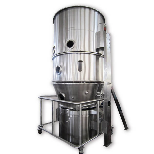
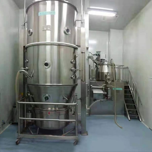
1. Inlet Air Treatment System
1.1 Primary and Intermediate Efficiency Filters
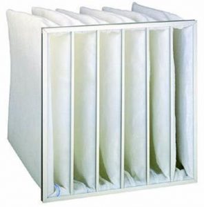
Inlet primary filter (0.15mm stainless steel screen), medium-effect bag filter (F7).
1.2 Heater
- Spiral wound sheet type heater.
- The heater steam inlet has a steam valve, which can adjust the pneumatic ratio.
1.3 High-efficiency Filter
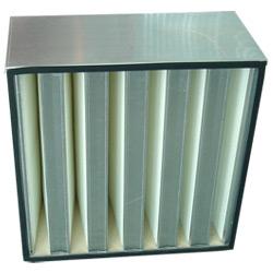
- Terminal high-temperature resistant high-efficiency filter (H13) with stainless steel outer frame to prevent thermal deformation.
- Quick-assembly structure.
- Differential pressure detection of high-efficiency filter, including quick interface to increase detection points.
1.4 Air Inlet Duct and Air Inlet Valve
- Temperature sensor speed interface for air supply duct near the bottom of the barrel.
- Automatic adjustment of pneumatic air inlet valve opening for regulating air inlet volume, linked with vacuum feed, thus regulating feed speed.
- It is fully open during process operation and fully closed during shutdown to prevent airflow backfilling and facilitate online cleaning.
- Adopt a frequency converter to adjust the fan speed to regulate the inlet air volume, precisely control the fluidization state and reduce energy consumption.
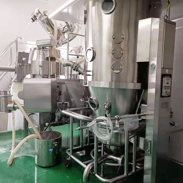
2. Host System
2.1 Equipment Base
- Overhanging head bottom cylinder, coupled with side support. Lowest point with quick-open
drain and valve for easy cleaning of equipment and floor. - The base is equipped with a quick-opening connection for the cleaning head.
- Vertical movable top ring above the base.
- Two lifting cylinders, vertically lifting the top ring to make the cylinder sealed.
- Silicone air bag is used to seal between the base and the top ring, and the use pressure is 0.3MPa.
2.2 Material Container
- Cart for container movement, height-adjustable universal wheels with brakes, and two horizontal guide wheels ensure balanced insertion of the cart.
- The manual mechanical device on the trolley for turning the container.
- Vessel positioning device to ensure the concentricity of the vessel and the main body.
- A window at the front and rear of the vessel for easy observation of the fluidization condition, with the gasket.
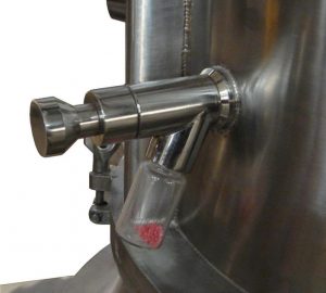
- The vessel is equipped with an airtight product sampler.
- The vessel is equipped with a quick interface for the temperature sensors.
- The sintered mesh at the bottom of the container avoids “secondary distribution” of airflow, is stronger than ordinary screens, has a long life, prevents powder leakage and is easy to replace.
- The container can be quickly disconnected from the trolley and tipped over for discharge in conjunction with the elevator.
2.3 Diffusion Chamber
- Suspended from the side support, it can be swung out horizontally.
- Multiple vertically aligned gun holes are reserved for chuck mounting, flush with the inside wall of the barrel after installation.
- Front and rear sight windows with gasket. Highly illuminated cold light sight lamp.
- Set up the inlet with inclined angle and quick release manual butterfly valve (or automatic pneumatic control butterfly valve, linked with the inlet valve opening automatically), using the equipment’s own negative pressure to feed the material to avoid material accumulation.
- A positioning stopper is set at the back of the diffusion chamber for judging whether the barrel is in place after being screwed in horizontally.
- There is a nozzle mounting seat for online cleaning which can be installed quickly.
2.4 Filtration Chamber
- Hand winch system: gear shifting mechanism makes filter lifting and lowering lighter; anti-slip automatic brake improves the safety of filter lifting and lowering; adaptive rotation function prevents steel rope from over-tensioning and breaking.
- The large diameter pulley made of non-metal material improves the stress condition between the steel rope and the pulley and increases the service life of the steel rope.
- The lower flange of the filter chamber is set with sealing silicone strip to avoid the material falling into the installation tank which is not easy to clean.
- Large tempered glass view window with gasket is set in front of the container. Used to observe the working condition of the product filter bag.
- Automatic pneumatic oscillating powder cleaning device to clean the product powder on the filter and make it fall back to the fluidized bed.
- Double chamber oscillation powder cleaning system, double filters alternately clean the powder and work continuously to ensure the fluidization state and realize continuous good drying effect.
- Anti-rotation mechanism of the filter bag holder, avoiding the bag holder turning to cause the trapping bag to be twisted and shortened, and the cylinder stretching to tear the trapping bag, keeping the filter bag flat and straight, which is conducive to powder cleaning and prolonging the service life.
- Vertical pressure relief safety door is set in the filter room, which will open automatically when positive pressure appears inside the equipment (pressure relief can be directed through the pipeline).
- Special structure of filter suspension, connected with the oscillating device, with automatic guiding and locking function. This function makes the filter follow the vibration of the cylinder with good transient response and improves the powder cleaning effect. Moreover, the steel rope is not under tension during powder cleaning, and the steel rope is not easy to break.
- The way of filter bag sealing and fixing changes the original filter bag turning out of the flange of the filter chamber and fixing outside, so that it is more in line with the GMP requirements for equipment
It is convenient for workers to operate. - Filter bag differential pressure detection, real-time monitoring of the differential pressure of the filter bag to reflect the ventilation effect of the system, as well as whether the bag is intact. The differential pressure is displayed on the screen and has a high pressure alarm function.
2.5 Support Column
- Support ears with barrel pivot for mounting the equipment barrel.
- Set temperature sensor pick and place positioning seat to regulate workers’ operation.
- Built-in air cable pipe and filter lift locking steel rope, external air cable pipe quick connection, with hand crank winch.
3. Atomization System
- Single head single pressure type nozzle, two atomization design, improve the “gas-liquid” mixing ratio, high-precision CNC machining, good quality atomization.
- All media from the coaxial gun body of their respective pipeline into the nozzle, the gun body with positioning pins and lock nuts.
- High-quality peristaltic pump, special step-less speed control drive.
- Manual adjustment of atomization air pressure by means of a pressure-reducing valve.
4. Exhaust System
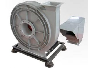
- The fan is a centrifugal high-pressure fan with vibration damper, explosion-proof type, installed in a non-purified room.
- The fan inlet is connected to the exhaust duct through a flexible joint to isolate fan vibration.
- Variable frequency adjustment of fan speed.
- Exhaust duct, carbon steel exhaust duct from the fan to the exhaust port of the filter room, installed in the non-purification room.
- The muffler is made of carbon steel to reduce the noise of the fan. The exhaust gas is introduced into the atmosphere by the piping system provided by the user after passing through the muffler.
5. Control System
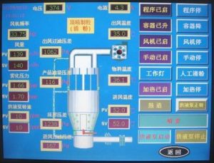
- Consists of an operating terminal and a main control electrical box, isolated operation.
- The operating terminal has a display meter, a touch screen (printer, if used), and indicator lights.
- The main control electrical box contains the PLC program controller, air switches, relays, contactors, inverters, all the necessary control appliances and all the wiring.
- PLC program control, manual and automatic program mode, and all necessary interlock protection.
- Set with test state and working state, two state interlock protection.
- Recipe parameter storage, three-stage safety setting.