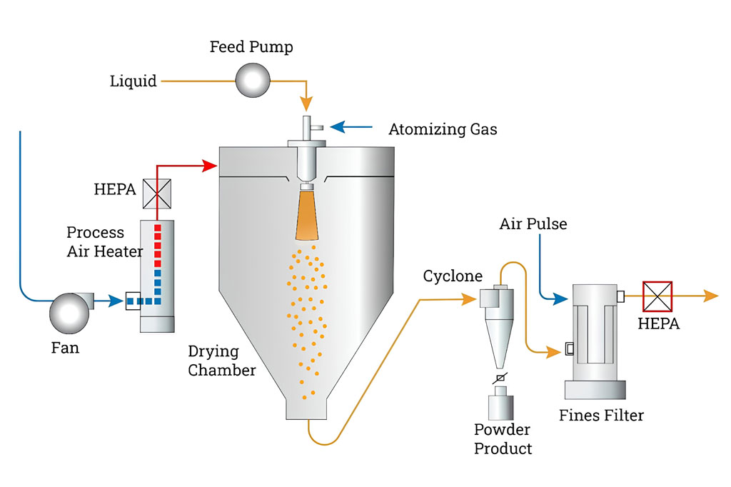
A spray drying process flow diagram is a visual representation that illustrates the complete pathway of converting a liquid feed into a dry powder using a spray dryer.
It maps out each stage of the process—from feed preparation to final powder collection—allowing engineers, operators, and designers to clearly understand system configuration, material flow, and operational logic.
1. Purpose of the Flow Diagram
The spray drying process flow diagram serves several essential functions:
- Process Visualization: It simplifies complex operations into an easy-to-understand schematic.
- System Design Reference: Engineers use it to design equipment layout and define process parameters.
- Operational Guidance: Operators rely on it to understand flow direction, key control points, and equipment roles.
- Troubleshooting Tool: It helps identify inefficiencies, bottlenecks, or process deviations.
2. Core Sections in the Diagram
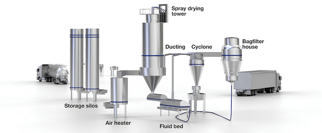
A typical spray drying process flow diagram is divided into several interconnected sections, each representing a specific stage of the drying operation.
2.1 Feed Preparation Section
This section shows how the raw liquid is prepared before entering the dryer.
- Storage tank (raw material holding)
- Mixing or agitation system
- Filtration unit (removal of impurities)
- Feed pump (controls flow rate and pressure)
The diagram indicates the direction of liquid flow toward the atomization system.
2.2 Atomization System
The atomization stage is where the liquid feed is transformed into fine droplets.
- Nozzle atomizer (pressure nozzle or two-fluid nozzle)
- Rotary atomizer (centrifugal disc)
In the diagram, this section is typically positioned at the top of the drying chamber, showing the dispersion of droplets into the hot air stream.
2.3 Air Handling System
This part of the diagram represents how drying air is introduced and conditioned.
- Air filter (removes dust and contaminants)
- Air heater (electric, steam, or gas)
- Blower or fan (controls airflow volume and pressure)
Arrows indicate the movement of heated air into the drying chamber, often in co-current or counter-current flow with the atomized droplets.
2.4 Drying Chamber
The drying chamber is the central component of the diagram.
- Depicted as a large vertical vessel
- Shows interaction between hot air and atomized droplets
- Illustrates evaporation of moisture and formation of dry particles
The diagram may include airflow patterns and residence time zones to clarify the drying mechanism.
2.5 Powder Separation System
After drying, the powder must be separated from the exhaust air.
- Cyclone separator (centrifugal separation)
- Bag filter or dust collector (fine particle capture)
The diagram uses branching flow lines to show how air and powder streams are divided and handled.
2.6 Powder Collection and Discharge
This section illustrates how the final product is collected and removed.
- Powder collection hopper
- Rotary valve or screw conveyor
- Packaging or storage system
The diagram emphasizes the controlled discharge of powder to prevent contamination or loss.
2.7 Exhaust Air Treatment
The final stage in the diagram focuses on environmental control.
- Exhaust fan
- Scrubber or secondary filter (if required)
- Chimney or outlet stack
Airflow arrows indicate the release of cleaned air into the atmosphere.
3. Flow Direction and Symbols
A spray drying process flow diagram uses standardized symbols and directional arrows:
- Arrows: Indicate the movement of liquids, air, and powder
- Lines: Represent pipelines or ducts
- Equipment icons: Simplified shapes for tanks, dryers, cyclones, and filters
- Control points: Valves, sensors, and instrumentation may be included
The diagram typically follows a left-to-right or top-to-bottom flow, ensuring logical readability.